Energy Solutions can help you reduce your fuel bills

Ut tellus dolor, dapibus eget, elementum ifend cursus eleifend, elit. Aenea ifen dn tor wisi Aliquam er at volutpat. Dui ac tui end cursus eleifendrpis.
Energy Solutions can help you reduce your fuel bills

Ut tellus dolor, dapibus eget, elementum ifend cursus eleifend, elit. Aenea ifen dn tor wisi Aliquam er at volutpat. Dui ac tui end cursus eleifendrpis.
An earthing system is to provide as nearly as possible a surface under and around a station which shall be at a uniform potential and as nearly zero or absolute earth potential as possible to ensure that, all parts of apparatus other than live parts, shall be at earth potential, as well as to ensure that operators and attendants shall be always at earth potential.
Also, by providing such an earth surface of uniform potential under and surrounding the station, hence there will be No Potential difference exist to shock or injure arise when short-circuits or other abnormal occurrences take place.
Earthing Electrode Consists Of Primary G.I./C.B Conductor (Outer Pipe) And Secondary G.I./C.B Conductor (Inner – Pipe/Strip) Galvanization is in as per requirement Microns. The Secondary Conductor is Inserted Inside The Primary Conductor. The Space Between The Primary And The Secondary Electrode Is Duly Filled With A Highly Conductive And Non-Corrosive Compound Which Safeguards The Electrode Getting Corrode Over A Long Period Of Time Under The Soil.
Back filling compound is noncorrosive either base on Graphite or base on Carbon has capacity to absorb & retain moisture from the surrounding. Being non soluble in water, it stays at the place and in not washed out by the rainwater/underground water. This mineral filling compound is highly conductivity improver compound.

Earth pit cover made from heavy duty FRP (Fiber Reinforced Plastic). FRP material provides high mechanical strength & zero water absorption. High Load bearing capacity ,Eco friendly – Green color body and green top cap matches the earthing environment. Eliminates expenses of cement / aggregates / masonry works. Easy to install & no expertise required. Light weight for ease in transportation. Ease in checking earthing during maintenance with Lockable arrangement Factory built holes for cable routing the strip or cable for interconnection.
A grounding system should be installed in a manner that will limit the effect of ground potential gradients to such voltage and current levels that will not endanger the safety of people or equipment under normal and fault conditions. The system should also ensure continuity of service.
If the magnitude of current dissipated into the earth is high, it seldom is possible to install a grid with resistance so low as to assure that the rise of a ground potential will not generate surface gradients unsafe for human contact. Then, the hazard can be eliminated only by control of local potentials through the entire area.


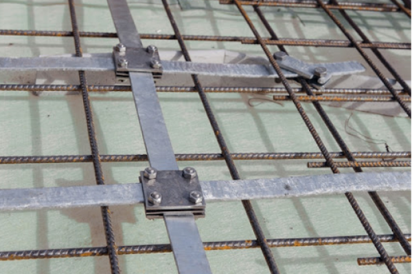
A Earthing Mat that combines a horizontal grid and a number of vertical ground rods penetrating into lower soils has advantage While horizontal (grid) conductors are most effective in reducing the danger of high step and touch voltages on the earth’s surface, provided that the grid is installed in a shallow depth (usually 0.3–0.5 m below grade), sufficiently long ground rods will stabilize the performance of such a combined system. For many installations this is important because freezing or drying of upper soil layers could vary the soil resistivity with seasons, while the resistivity of lower soil layers remains nearly constant.
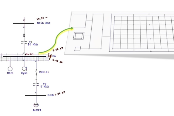
By using IEEE 80 & IEEE 665 Earthing Mat Design carried out with help of software tools with Interactive Result of potential at earth’s surface, allowable currents against fault currents ,Ground grid configurations showing conductor & rod diagram with report of step, touch, & absolute potentials inside & outside grid area.
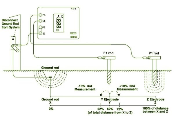
First of all , the earth electrode of interest must be disconnected from its connection to the Equipment. Second, the Earth tester is connected to the earth electrode Then, for the 3-pole Fall-of-Potential test, two earth spike rod are placed in the soil in a direct line away from the earth electrode. Normally, spacing is equal to length of earthing electrode is sufficient.
A known current is generated by the Earth Tester between the current spike rod P1 and the earth electrode, while the drop in voltage potential is measured between the voltage spike rod E1 and the earth electrode. Using Ohm’s Law (V = IR), the tester automatically calculates the resistance of the earth electrode.

For accuracy of result you need to increase the distance between the earth electrode under test and the voltage rod E1 by keeping the current rod position constant until the measured values remain fairly constant when repositioning the voltage rod E1.
Connect the Earth tester as shown in the diagram. Press START and read out the resistance value of the earth electrode under test.